SPECIALIZED WELDING AND HANDLING SYSTEMS - TELWIN & FORSTER SYSTEMS


WELDING HANDLING SYSTEMS - FORSTER SYSTEMS
SPECIALIZED WELDING :
Contact us for Technical Details and Price List on : EMAIL:SALES@WELDNBRAZE.COM


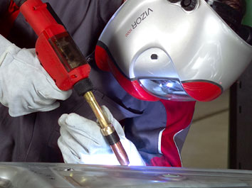
Spot Welding
|
Seam welding
|
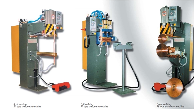
RESISTANCE WELDERS :
Types of machines
1) Spot welders, named because the weld looks like a spot, normally 6mmdia to 8mmdia and round in appearance and when set properly silver in the middle with a 1,5mm – 3mm black ring around the outside of the silver area.
2) Projection welders, named because they have flat type electrodes and small dimples have been placed into the steel part to be welded. Parts such as weld nuts & bolts are projection welded.
3) Butt welder and Flash Butt welder, these machines weld various sizes of bar together, i.e. steel window frame corners, round section, flat and square section, tube sections both square and round. The Butt welder pushes the parts together and the weld takes place whereas the flash Butt welder slowly brings the parts together thereby creating a sort of arc weld that throws sparks everywhere.
4) Seam welder, named because the machine is used to weld a seam along flat plate, 0,6mm – 2mm thick. These welds can be either gas tight or what we call roller spot welder where the finished welds looks vaguely like a sowing machine stitch. This process is used on parts such as fuel tanks and gas vessels.
Most of the above machines 50kva series 90, the 100/150kva Powerspot, the 250kva and 450kva projection welders and the 250kva seam welder are operated by an air cylinder that opens and closes the heads but machines such as the 35kva foot, 25kva Handispot and the 35kva Hotspot are foot operated and use an internal spring to place pressure on the weld area during welding.
Explanation :
All the resistance welders work with same basic method. You put relatively high voltage (380volts) and low amp (100amps) in one end of the machine and you get low voltage (10volts) and high amp (10 000amps) out the other end, obviously these are not actual inputs and outputs but they give you some idea about what happens inside the machine. To breakdown the operation into a sequence of events this is what happens on both the foot machine and a typical air machine.
1) The operator holds the steel parts to be welded in the spot welder.
2) He then pushes down the foot pedal and the tips close onto the parts to be welded.
3) Once the parts are securely held by the tips the transformer inside the machine is switch on for a short period sending electricity into and through the parts, this heats the parts up at the point of contact between the tips and a weld takes place.
4) The machine is then opened and the parts removed.
The electric is converted from high volts / low amps to low volts / high amps by a transformer inside the machine. The word transformer is self explaining as it changes or transforms the electricity from one type to another.
Electrical Power :
All the above machines are powered by 380volts supply but in most cases only two of the available three phases are used. As a simple rule of thumb the following supplies and cable sizes are suggested. Please note that this is a guide only and you should always consult with a fully qualified electrician before any installations are undertaken.
1) 25kva foot machine 10mmsq cable 60amp supply
2) 35kva foot machine 16mmsq cable 60amp supply
3) 50kva foot/air machine 25mmsq cable 80amp supply
4) 100kva air machine 50mmsq cable 160amp supply
5) 150kva air machine 50mmsq cable 250amp supply
6) 250kva air machine 90mmsq cable 350amp supply
Water and Air requirements:
1) 25kva foot machine 20l/min no air
2) 35kva foot machine 20l/min no air
3) 50kva foot machine 25l/min no air
4) 50kva air machine 25l/min 2 – 6 bar
5) 100kva air machine 40l/min 2 – 6 bar
6) 150kva air machine 40l/min 2 – 6 bar
7) 250kva air machine 60l/min 2 – 6 bar
On the machines that use air the usage of air is roughly as follows; please note this is a guide only and differences will occur depending on cylinder size and stroke of tips or platens. The air usage is roughly based on a tip gap of about 25mm
1) 50kva spot welder 2l per stroke
2) 100kva spot & projection (125dia) 5l per stroke
3) 150kva spot & projection (125dia) 5l per stroke
4) 250kva projection welder (200dia cyl) 10l per stroke
5) 250kva projection welder (250dia cyl) 12l per stroke
6) 250kva seam welder (125dia cyl) 5l per stroke
What a resistance welder can do for you:
Spot welder;
The resistance spot welder are used to weld clean cold rolled mild steel sheet, and stainless steel sheet, wire mesh, plates to clean rolled round tubing, weld nuts & weld bolts, studs.
Projection welder;
The resistance projection welder can weld more than one weld at a time and can be used to weld small plates to other plates, mesh, girding, round bars, weld nuts & bolts.
Butt welder;
Normally used on wires, small dia round & square bars.
Flash butt welder;
Used on larger sections than those on the Butt welder, window frames being the most common part to be welded.
Seam welder;
Used in the automotive trade for fuel tanks, solar heater panels, pressure plates in the mining industry and other areas where gas tight welds are needed.
Process :
1) Electricity is generated in a power station where it passes into copper wires and sent out to the cities.
2) The electricity arrives in the industrial areas and passes through copper wires inside a transformer to be changed or converted into 380volts
3) The electricity comes into your factory, passes through your switch or distribution board and finally arrives at your machine and all the time through copper wiring
4) Once at the machine it passes through a copper winding in the transformer, into a copper buss bar and flexible shunt into copper arms and tips
5) At long last the electricity arrives at the welding tips that are manufactured from hard copper and SUDDENLY!!! There is a piece of steel in the way.
6) The steel doesn’t like the idea of electricity passing through it and tries to RESIST!!! The passing of electricity and starts to get hot.
7) Finally the steel melts, the electricity gets through the joint / parts / steel after creating a hotspot (weld)
8) The electricity returns all the way back to the power station through copper wires.
As shown in the description above the only area where a resistance to the passing of electricity through the circuit, that is basically all copper or other good conductive materials i.e. copper, brass, aluminum is at the point between the tips and this is where the weld will take place.
Elements needed to make a resistance weld:
1) electricity
2) pressure
3) water
4) time
1) As discussed above we USE ELECTRICITY!!! Because its what makes the weld take place. As it passes through the weld area it makes this area get hot finally melting the steel in this area and sort of gluing the steel together.
2) Obviously we USE PRESSURE!!! To hold the parts together while the electricity passes through the parts. There are two ways of holding the parts together. On small machines of low power in can be carried out using a spring but larger machine use air and sometimes even hydraulically.
3) So you have stuck all this electricity into a piece of steel and its just got bloody hot, well what can we do to get rid of all this heat floating about, USE WATER!!!!. The water is inside the tips, transformer and other places to control this heat and remove it from the machine as quickly as possible to stop possible damage to the machine and tips.
4) Finally we USE TIME!!! To control the size of the weld and heat being put into the weld area. By limiting or controlling the time the machine can weld for we can control the size, look, finish and strength of the weld.
Machines & Bits and Electrodes:
1) The magic of the machine and its bits
2) So lets discuss the bits.
3) General discussion of air system in air operated machines
4) General discussion of the water system used on machines.
5) General discussion of the electrical system in the machine
The magic of the machine and its bits
Machines basic component parts:
1) A frame to support all the stuff
2) A transformer to convert electricity.
3) A timer control system to control the machine.
4) A foot pedal (on foot operated machines) to close the tips.
5) An air cylinder and air solenoid (fancy name for a valve on air operated machine) to close the tips.
6) An electric foot switch to start the machine.
7) Upper and lower arms (spot welder) or platens (projection welder) or seam head (on seam welders).
8) Flexible welding shunt. (on virtually all machines)
9) A switch to switch electricity to the transformer
Bits and Electrodes:
The frame comes in many shapes and sizes to suit the type of machine, its size and its application.
The transformer is hidden inside the machine frame. All transformers are built into a yellow zinc plated box where the internal guts of the transformer are cast in resin. manufactures transformers from 25kva to 600kva sizes This type of transformer is called an “encapsulated” transformer. You also get transformers that you can see the insides. We sometimes call these “open wound” transformers. Inside the transformer there are normally three major parts,
1) Primary winding (where the electricity comes into the transformer before being changed or transformed)
2) The secondary winding (where the electricity leaves the transformer after being changed or transformed)
3) The steel cores that create a magnetic field inside the transformer to help change the high voltage / low amperage to high amperage / low voltage.
The timer control system is the clever part of the whole machine. The timer control is an electronic device often looking something like an old fashioned radio. Depending on the type of machine you use the timer selected will contain the functions and facilities needed to create a weld. Here is a list of some timers and what for and where they are used.
1) T1AP1 or T (timer), 1 (single program to operate one machine, head or welding gun), A (asynchronous meaning the timer is not a digital timer or in more simple terms it works with knobs), P (the timer uses phase heat control or more simply it has the ability to increase or reduce the heat with a knob). 1 (this 1 means it has the ability to weld only once in a sequence.
2) Minipak timer WK-MPS-01, MPS (micro processor system) 01 (single program to operated one machine, head or welding gun) is basically the same as the above timer but it is fully digital and has the ability to weld twice in a sequence.
3) Weldpak Timer WK-MPS-08 WK MPS (micro processor system) 08 (eight program to operated one or more machines, heads or welding guns) is basically the same as the above timer but it is fully digital and also has the ability to weld twice in a sequence. This timer has the further ability to pulse weld up to 99
4) Smartpak Timer WK-MPS-16 WK MPS (micro processor system) 16 (sixteen program to operated one or more machines, heads or welding guns) is basically the same as the above timer but it is fully digital and also has the ability to weld three in a sequence. This timer has the further ability to pulse weld up to and is programmed standard with constant air pressure and constant current capabilities. The Smartpak timer has up-slope, down slope and seam welding capabilities.
The T1AP1 and Minipak timers or most often used in foot pedal machines, the Weldpak & Smartpak in machine where more control of the welding characteristics are needed to ensure higher or more consistence welding quality.
The foot pedal is used by the machine operator to open and close the welding tips on smaller or lower power machine. It is part of a lick / leverage system the uses springs to achieve the pressure on the weld area.
The air cylinder & solenoid replace the foot pedal used in small machines with a more consistent, faster and higher pressure system than that achieved by means of a foot pedal, levers and springs. Most larger types of machine use air cylinders in sizes ranging from about 80mm as on the Econospot & Series 90 50kva to 250mm on the large frame projection welders. All these cylinders get air fed to and from them by means of an air valve (solenoid). On the smaller machines the solenoid is about ¼ inch size and the larger cylinders that use air quicker will use a ½ inch solenoid system.
The electric foot switch is used only on air operated machines to start the operation of the machine. Some machines use hand operated switches to achieve the same result.
Upper & Lower arms (spot welder) or platens in projection welders are used to support the welding tips or electrodes while welding takes place.
Flexible welding shunt. With the movement of the welding tips up and down we only fix one side of the machine and hold it stationary. This is called the fixed arm. The arm that moves, the moving arm, needs to have some means of supplying this high amperage electricity to the tips. The electricity passes through what is called a flexible welding shunt. These can be laminated, (lots of thin copper plates laying one on top of the other) or a braided shunt that looks like a very thick woven copper wire
A switch to switch electricity to the transformer. This can have several clever names i.e. S.C.R (silicon control rectifier), thyristor pack, ignitron replacement unit, AC switch but it doesn’t really matter what it is called it is still just a glorified switch.
Air system in air operated machines:
The air system that opens and closes the machine air cylinder has a set route through the machine that is common to all machines. The following is where it goes and what happens.
1) Air enters the machine through a device called a FRL, this is an abbreviation for Filter, Regulator, Lubricator. These devices are fitted to the outside of the machine and come in two basic sizes. They are ¼ inch and ½ inch. As can be seen by the description of the device it first filters the air for impurities like dust and water catching the water in a water trap. The air can then be regulated by the regulator unit and the regulated pressure is indicated by means of a dial gauge screwed into the front of the regulator, finally the air that has been cleaned and regulated has oil put into it to lubricate the air cylinder and the bushes within the cylinder assembly. This function is carried out by the lubricator that drips a small amount of light machine oil into the air with every stroke of the air cylinder.
2) The air now heads to the solenoid air valve. Once at the valve the air flow is stopped as the valve is normally in the closed position stopping air from entering the top of the cylinder. While the valve is in the closed position air is allowed to pass to the bottom of the cylinder to keep the cylinder in the up or open position. The valves are in most cases electrically switched open & closed by the welding timer control.
3) When the timer control switches the valve, air is allowed to pass on towards the top of the air cylinder allowing the cylinder to close. at this time the valve also allows the air in the bottom of the cylinder to exhaust out of the system.
4) This is how the air operates the air cylinder that opens and closes the welding tips.
Technical stuff concerning air. The air must be clean and not contain excessive water or condensation. Air pressure to the machine must be constant and not subject to fluctuations. Air pressure to the FRL should be about 6bar. Pipes supplying air to the machine should be of a minimum internal dia of 12mm and preferably 16mmdia.
Water system used on all machines:
..We just made enough heat to melt steel in less than a second, we made a weld and then, what do we do with all this heat that is floating about in the weld area and in the machine. If we don’t do something we are going to damage the tips and if we are not careful the machine as well. The most common method to cool something down is to use water
Well let’s introduce it to this process to help cool the machine and its tips. Firstly, we obviously don’t want to waste the water so we use a cooling system, chiller unit. The Chiller unit is a simple evaporation type cooling unit.
Use of water to cool down all welding components/system
1) Water leaves the cooling tower / chiller unit and enters the welding machine at the inlet port, once in the machine it may be split into separate circuits or pass through one inline circuit.
2) When the water is an inline system (one pipe connecting everything one after the other) the first and most important part to cool is the transformer switch. (AC Switch / S.C.R / Thyristor).
3) Next in line to be cooled is the transformer unit
4) Finally the welding tips need to be cooled.
5) After cooling the tips the water passes through the outlet port in the machine and then back to the cooling tower / chiller to be cooled.
6) Cool water is now sent back to the machine.
Technical stuff concerning water in a cooling system
Water needs to flow through the machine easily without blockages, the water pressure going into the machine should be about 3bar and the outlet pressure must not be more than half of the inlet pressure or 1,5bar. Temperature going into the machine should be about 20deg – 25deg C. the water should not be dirty. NEVER add cleaning agents such as HTH, acids or flocculants without first consulting . Pipes supplying water to the machine should be of a minimum internal dia of 12mm and preferably 16mm/dia.
/
General discussion of the electrical system in the machine
So we got water and air going through the machine. The air makes things go up and down, the machine will run cool because of the water and now for the electrical bit to make the bang.
Most machines available in South Africa no matter where they coming from,will use two phases of the three available 380v – 400v of electricity at 50hz. Depending on the size of the machine they will have a lesser or greater need to be fed some amps to do the work intended but what ever their specific needs are they all work more or less the same way.
1) your electrical supply from your Distribution board is connected to the on/off switch fitted to the machine.
2) Electrical power is (when the switch is switched on) passed through the switch and on into the machine
3) One phase is supplying power straight to one of the two connections on the transformer and the other phase goes to the switch (AC Switch / S.C.R / Thyristor).
4) While this switch is closed no electrical power can flow through the system. When the operator uses the machine the timer control triggers the switch which opens and allows electrical power to flow from the switch to the other connection on the transformer.
5) The transformer (lets say it is 50kva air machine) gets electrical power and starts to change 380volts with 80amps supply to 6volts with 15000amps.
6) This 6volts & 15000amps then passes out the transformer along the arms and into the tips.
7) As discussed above the steel being placed between the tips by the operator tries to resist the flow of electricity, the steel gets hot and a weld takes place.
8) The electricity passes back for the tips, into the transformer, through the switch and back to the distribution board.
Never undersize the supply cables:
Otherwise, they will run hot and might start a fire or electrical short. Make sure all installations are undertaken by a qualified electrician.Always earth your machinery!
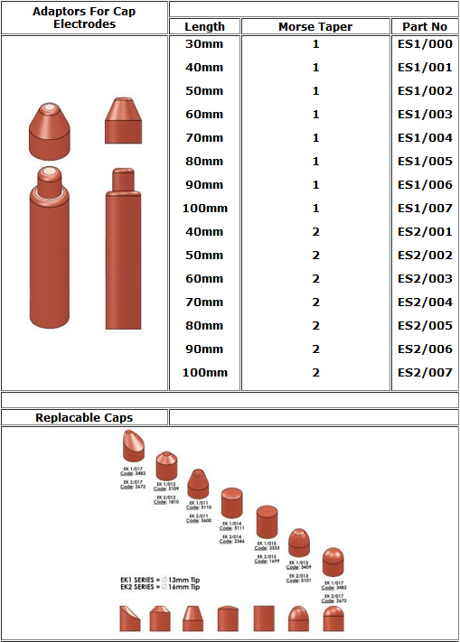
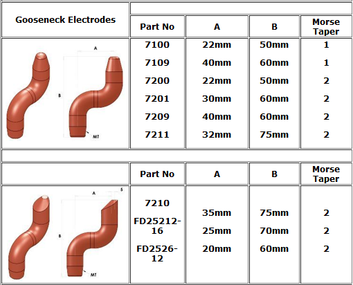
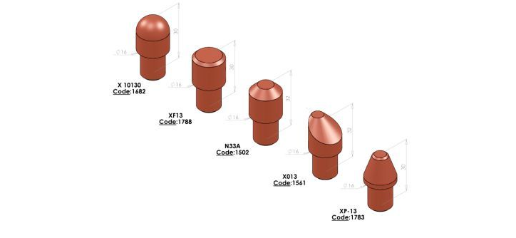
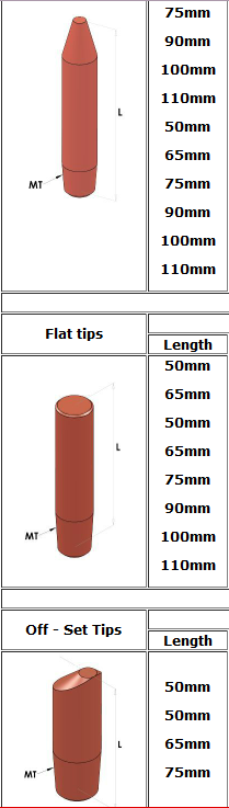
VARIOUS TIPS & ELECTRODES & ADAPTERS :
|
|

|
|
|
|
|
google-site-verification: google231c230fc8f05942.html